Coolant/Anti-Freeze
Oil and filter
Cam lube (a/r)
Thread locker - red
Thread sealant
Permatex Ultra Copper gasket sealer
Spray cleaner or solvent for gasket surfaces (brake cleaner works well)
Rags and paper towels
Towels or fender cover to protect the finish
a/r = as required/needed
|
Camshaft
Lifters (a/r)
Pushrods (a/r)
Rocker Arms and Nuts(a/r)
Valve Springs
Valve Cap Locks (keepers)
Valve Caps (retainers)
Valve Seals (a/r)
Valve Spring Shims (a/r)
Valve Spring Locators (a/r)
Timing gears and chain
|
Valve cover gaskets (a/r)
Intake Manifold gasket set
Front Cover gasket set
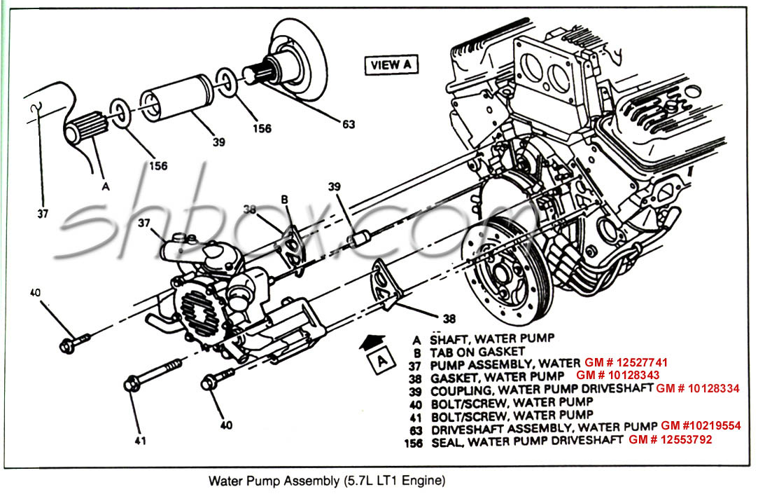
Water Pump gaskets (if not incl in timing set)
Water Pump O-rings
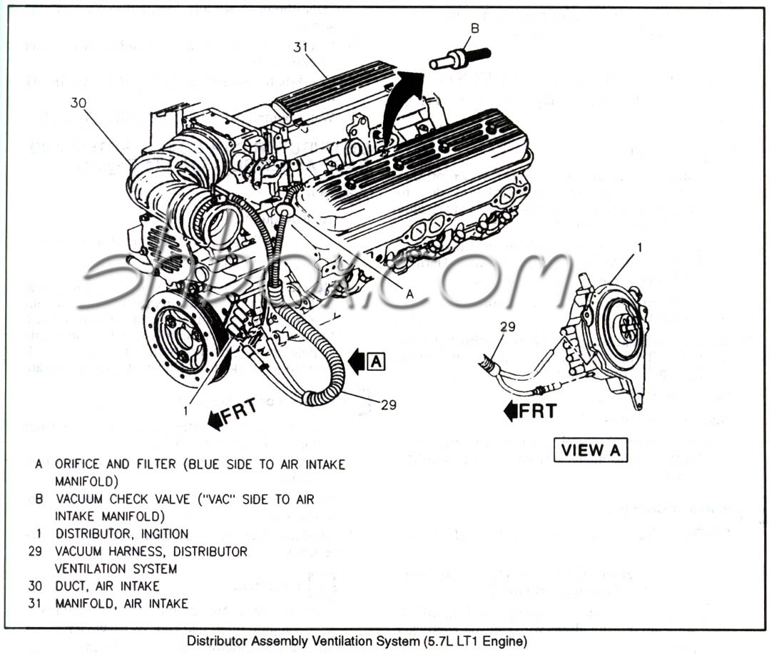
Opti-spark O-rings
Oil Pan gasket (a/r)
|
Decent set of hand tools
Valve Spring Compressor
Magnetic Pick-up tool
Valve Spring Height Micrometer
or
alternate method of measuring spring height
Torque Wrench
3 claw puller (a/r)
Crankshaft hub removal/installation tool
Optional studs or pins for lining up intake on re-install
Fuel pipe connector disconnect tool (3/8" and 5/16")
Gasket scraper
Three 5/16-18x4" bolts (a/r)
|